How to Measure the Axial Ratio of the Circular Polarizer
Print|
How to Measure the Axial Ratio of the Circular Polarizer Two methods are usually used to measure the axial ratio of the waveguide circular polarizer: 1. Install the antenna to measure the antenna axial ratio; 2. Directly measure the axial ratio of the waveguide circular polarizer. Among them, the method of installing antenna to measure antenna axial ratio is a relatively common measurement method, but this method will introduce interferences from space and antennas. In addition, antennas and other systems may not be convenient to test with waveguide circular polarizers in some cases. So, it is necessary to test the axial ratio of the circular polarizer separately. In this blog post, A-INFO introduces a simple direct measurement method of the axial ratio of the waveguide circular polarizer.
Test equipment and requirements
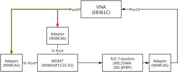
Testing process 1. Calibration
According to the block diagram, the Port1 of the vector network analyzer is connected to the V-Port and H-Port of WOMT respectively, and the system insertion loss of IL_v1 and IL_h1 without the waveguide circular polarizer are measured. Note that the Circular to rectangular waveguide transition is required to keep the same polarization as WOMT’s during the test.
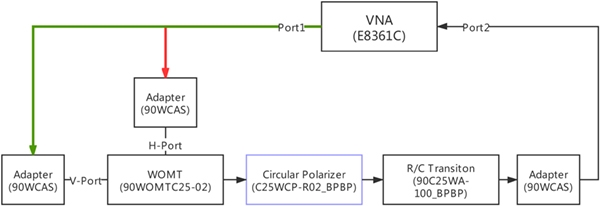
2. Test According to the block diagram. The vector network analyzer needs to turn on the time domain gate to filter out the reflected signal. Port1 is connected to the V-Port and H-Port of WOMT respectively, and the insertion loss IL_v2 and IL_h2 including the waveguide circular polarizer is measured. During the test, it is necessary to rotate the Circular to rectangular waveguide transition so that the Circular to rectangular waveguide transition and WOMT maintain the same polarization, and the time domain gate needs to be adjusted according to the actual situation.
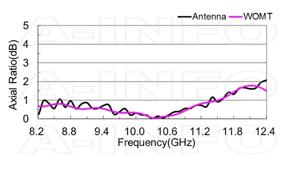
3. Calculation By comparing IL_v1 and IL_v2, IL_h1 and IL_h2, the information of the V and H components of the circular polarizer can be obtained. Simply, the amplitude difference between the two can be directly used as the axis ratio.
Test curve comparison
|