
Description
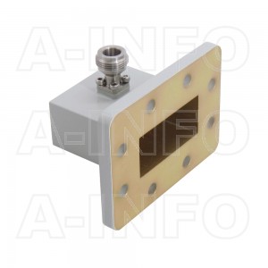
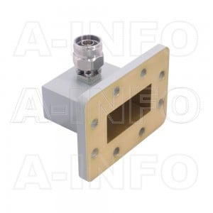
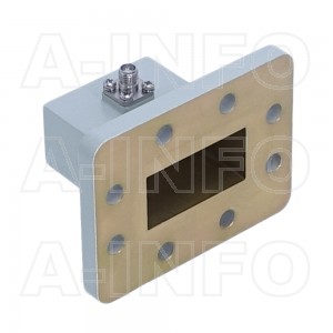
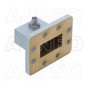
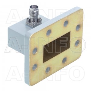
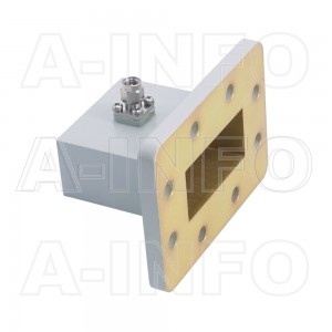
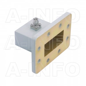
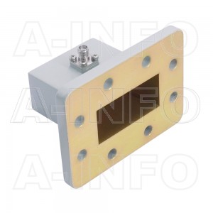
Dual linear polarization corrugated feed horn antenna LB-ACH-159-10-T02-A, operating from 4.90 to 7.05GHz with a nominal 10dB gain and low VSWR 1.30:1 with rectangular waveguide WR159 output. The waveguide flange is FDP58(UDR58). The corrugated feed horn antennas are precisely fabricated to minimize the tolerance of aperture corrugated groove, and have features like: rotationally symmetric radiation pattern, low cross polarization and stable amplitude taper within operating frequency. The model LB-ACH-159-10-T02-A has dual linear polarization and ideally suited for reflector feed, CATR and other applications. The corrugated feed horn antennas have an option of integration with absorber for better gain flatness and radiation pattern.
Technical Specification
| Model | LB-ACH-159-10-T02-A |
|---|---|
| Frequency, Min (GHz) | 4.9 |
| Frequency, Max (GHz) | 7.05 |
| Waveguide Type | Rectangular |
| Waveguide Size EIA WR | WR159 |
| Gain, Typ (dBi) | 10 |
| Polarization | Dual Linear |
| 3dB Beamwidth, E-Plane, Typ (Deg.) | 56 |
| 3dB Beamwidth, H-Plane, Typ (Deg.) | 57 |
| 10dB Beamwidth, E-Plane, Typ (Deg.) | 103 |
| 10dB Beamwidth, H-Plane, Typ (Deg.) | 107 |
| Cross Pol. Isolation, Typ (dB) | 45 |
| Port to Port Isolation, Min (dB) | 40 |
| Port to Port Isolation, Typ (dB) | 50 |
| VSWR, Typ | 1.30:1 |
| Output Type | Waveguide |
| Flange Style | Round |
| Flange Type | Cover |
| Flange Designation | FDP58(UDR58) |
| Body Material | Al |
| Finish | Chemical Conversion Coating, Gray Paint |
| Figure | A Type |
| Size, W (mm) | 102 |
| Size, H (mm) | 120.7 |
| Size, L (mm) | 445.8 |
| Weight, (kg) | 2.394 |
| Application | General Purpose Indoor & Outdoor, Fixed |
| Solution for | Reflector Feed, CATR |